
- #Max6675 v1.2 arduino nano pinout install#
- #Max6675 v1.2 arduino nano pinout zip file#
- #Max6675 v1.2 arduino nano pinout portable#
I still wanted to employ some keypad functionality to make the device portable for remote operation. So, the easiest way to experiment is to USB-connect the Arduino Uno and open the sketch in the Arduino IDE.

Like fancy commercial controllers, I wanted to enter every parameter and control every function using the five navigation buttons on the LCD keypad display shield, but that is beyond this project’s scope (i.e., beyond my capability). Simply copy the PID_v1R folder to your Arduino library folder and enable in menu >Sketch>Include Library.
#Max6675 v1.2 arduino nano pinout zip file#
This new library is contained in the software zip file in the downloads for this article. This sketch modifies the excellent PID_v1 library from Brett Beauregard ( ). The module’s five interface pins fit neatly into the A1-A5 holes on the LCD keypad display shield.

#Max6675 v1.2 arduino nano pinout install#
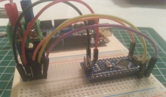
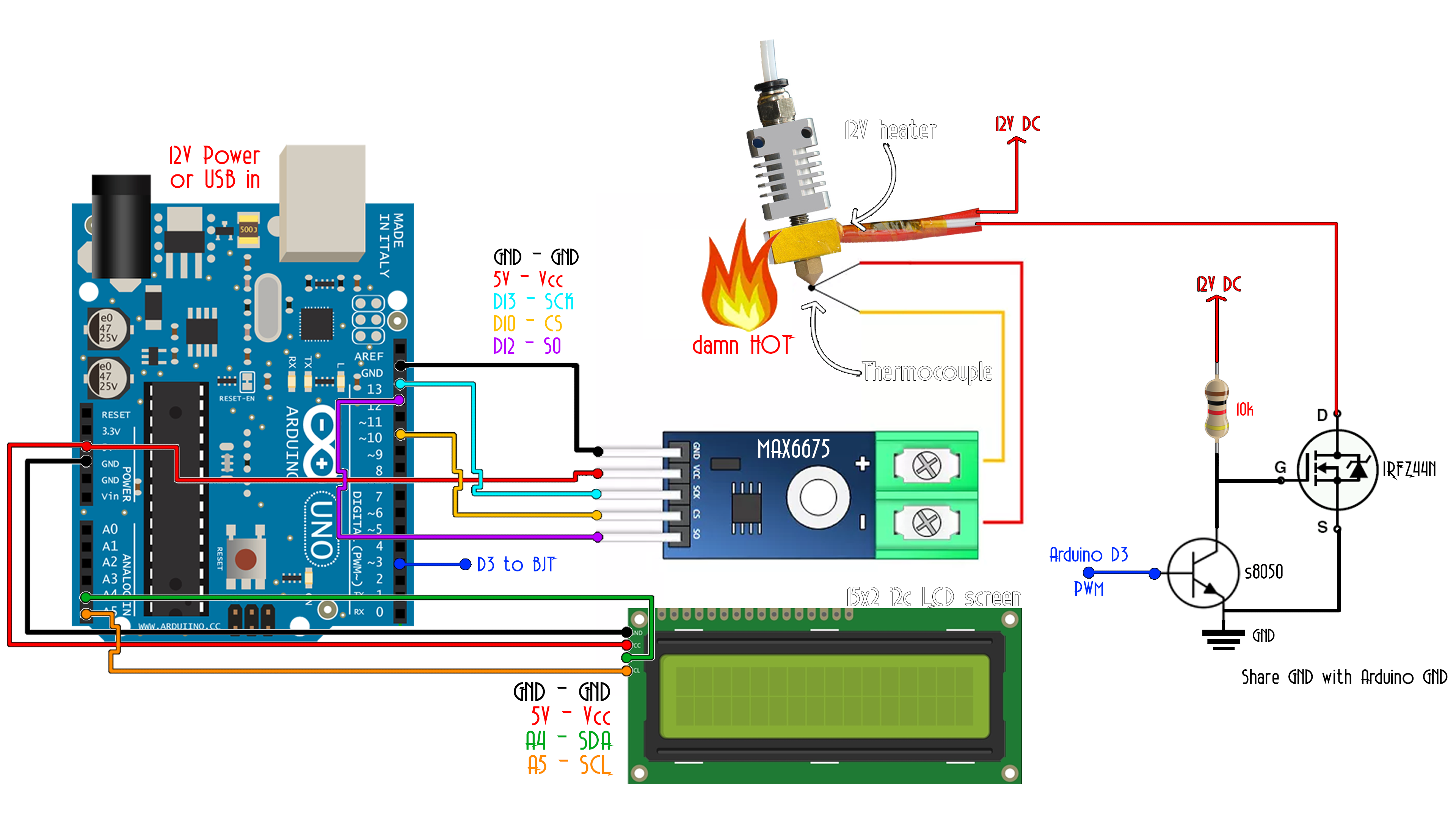
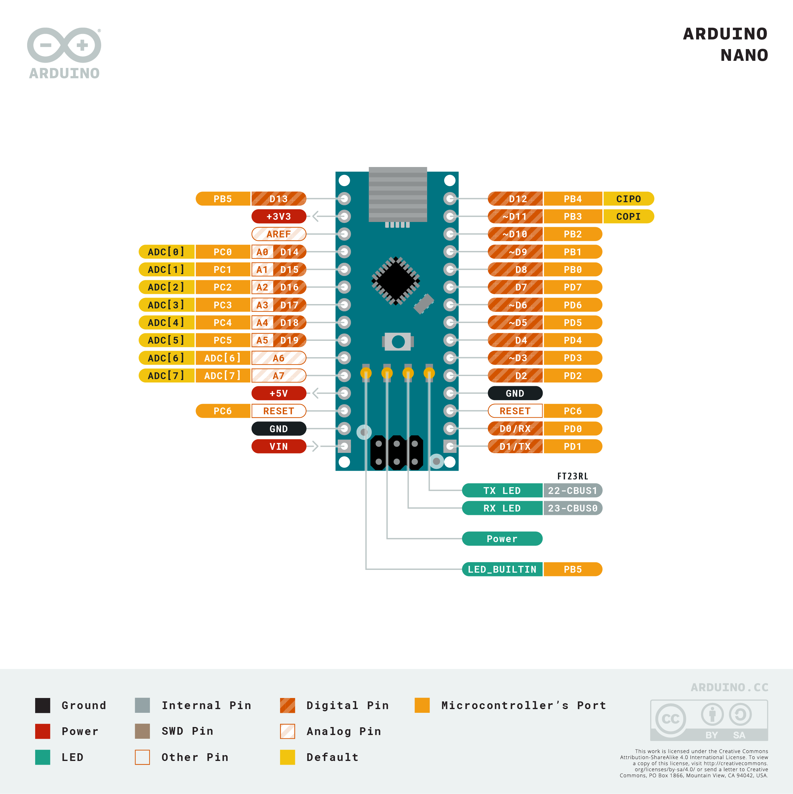
Install the Arduino MAX6675 library for both Fahrenheit and Celsius temperature measurements. The five-pin electrical interface consists of two power pins and three data I/O pins. This temperature sensor module incorporates the MAXIM 6675ISA eight-pin integrated circuit soldered to a PCB (printed circuit board) substrate. This hardware is supported in the standard Arduino IDE library. This is a popular Arduino shield that integrates a 16-character by two-line LCD display with five navigation buttons and one reset button. An Arduino Nano and breadboard were used for actual SSR bench testing purposes. Two optional LEDs provide a visual indication of PID variable outputs. Fortunately, this leaves digital pins 3 and 11 (both on 16-bit TIMER2) available to use for Pulse Width Modulation (PWM) outputs: pin 11 to heat (plus +) pin 3 to cool (minus -). Soldering the MAX6675 module is optional for initial testing ( Figure 3).Īnalog pins A1-A5 were enabled for digital function to provide temperature sensor power and communication. Assembly is simply a matter of observing the correct orientation and fitting the sub-units together. This PID controller device consists of three sub-units: an Arduino Uno R3 MAX6675 thermocouple temperature sensor and1602 LCD keypad display. Once programmed on a PC (in the normal Arduino IDE way), the unit can be taken out to the process shed for stand-alone operation.įIGURE 2. The Arduino controller that I eventually made stores a number of time vs. Refer to Figure 1.įIGURE 1.Thermal application block diagram. The thermal control system is composed of the PID controller, solid-state relay (SSR), and 1,500W hotplate. temperature profile to process the vegetables properly.

The farmer’s canning application required executing a specific time vs. For these reasons, I decided to build an Arduino PID temperature control unit. Plus, the Arduino integrated development environment (IDE) is easy to install and remarkably easy to use. The Arduino product family provides inexpensive hardware for the home builder. Of course, many fine industrial process controllers already exist (say, from Omega), but I strived to learn their secrets and do it smaller and cheaper. So, when a local farmer asked me to automate a vegetable canning process, I took it as a challenge to physically realize a PID temperature control device. » Skip to the Extras Advanced Process Control Technology for little cost.īeing a devoted nerd, I’ve long been fascinated by Proportional Integral Derivative (PID) process control.


 0 kommentar(er)
